3D Central
Train - Passenger Car
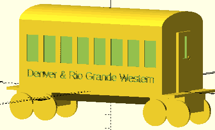
Getting people from here to there by rail requires better accommodations than a bare boxcar (well, for most people). Minimum benefits are seats and windows, for sure.
At this stage of the project, the windows are just partially there and there are no seats. Maybe the next round.
Before this, I have convinced myself that I find it easier to visualize where pieces fit and how big they are by using fixed sizes for each part. However, after a year of this, I'm beginning to think it may be that I am about ready to commit to the use of variable control from the very start of each project. (Could my wording be more wishy-washy?)
Between doing the hard-coded version00 of this passenger car and version01, the variable-based version, I designed the Easter Island figurine. That was done attempting variable control from the beginning, with good success, I think. It is also interesting to me that it has become possible to juggle several projects at the same time. A year back, it was one at a time!
The code of passenger car version01 turns out to be much more compact because of starting over and rethinking/redesigning modules, all based around the zero point making each component easier to reuse. Each end of the car was a separate set of code in version00. In version01, a simple rotation puts the opposite end in place. Likewise, the "left" side of the car is a simple rotation of the "right" side which got designed first.

I am not sure you will approve of my approach. Every design decision comes out of the thinking process of the person doing the design. You might approach this job very differently from the way I did. Still, looking through the code of both versions MAY offer you some insights to consider when you design your next project.
A reminder:
The print is intended to just be the top of the passenger car. It is designed to fit on the flatcar which will need to be printed separately.
As you can see from this section, "everything" is in a module. The four modules are found above this execution section in passenger01.scad. The other benefit is how easy it is to focus on each part by commenting out what you don't want to show. See mockup();.
// EXECUTION SECTION
roof();
// far end
carend();
// near end
rotate([0,0,180])
carend();
// near side
side();
// far side
rotate([0,0,180])
side();
// remove mockup for final print
// mockup();
Let's focus on the carend(); module to look at how a reusable module makes it easy to design one end in place and just "reverse" the module to make the opposite end. The sides work the same balanced way.
The length of variable "carlen" used here is carried over from the flatcar design. On my printer 145mm is an effective maximum in one dimension. The box of the passenger space is not quite so long, leaving room for a platform at each and for a ladder to hang under the car end. (I have not designed the ladder yet. I actually think the ladders should be part of the flatcar, now that I'm really thinking about it.)
module carend(){
    // setup for far car end
    // near end will just be a rotation
translate([carlen*.85/2-2,-carwid*.5,0])
cube([2,carwid,carht]);
 //far door
difference(){
translate([carlen*.85/2,-carwid*.15,0])
cube([2,carwid*.30,carht*.9]);
translate([carlen*.85/2-1,-carwid*.05,carht*.5])
    cube([4,carwid*.1,carht*.33]);
}
//knob
translate([carlen*.85/2+1,carwid*.1,carht*.5])
sphere(2);
}
The entire design is centered on the intersection of the X and Y coordinates (but all above zero on the vertical, Z axis). That means the "far" end of the car is 85% of half the car length in the positive direction along the X axis translate([carlen*.85/2-2,-carwid*.5,0]) cube([2,carwid,carht]);. Though it has taken me time to understand this relationship, it has been very useful to grasp. It means making the "near end" is a simple rotation of the code around the Z axis. None of the numbers have to change. The rotation makes the values effectively reverse for the near end putting the end 85% of half the car length negative along the X axis, balanced with the far end. The relationship of the sides is the same, one half the car width in the positive Y direction, the other balanced half the car width in the negative on the Y axis. The ID of the rail line and windows and even the doorknob, being part of the module, also appear in the right places on both ends and both sides.
I do realize that the explanation in the preceding paragraph would be a bit clearer if the car ends were set all the way at each end of the 145mm car length. Then I could have described each end as being half of the car length from the place the axis lines cross. It did take me a bit of fiddling to understand and implement the balanced shortening of the passenger box to just 85% of the flatcar on which it will sit. On modern passenger cars, of course, the doors are on the sides of the car instead of the ends. The ends are connected with a flexible passage between cars, no need to go outside as you walk to the dining car. (At least, that was the way it worked the last time I actually got to take a cross country ride on a train.)
Available Files:
SCAD files for study/modification and STL files for quick prints
passenger00.scad - just so you can examine the raw original design thinkingpassenger01.scad - passenger01.stl - for study of the revised version and to print
GPL3 License