3D Central
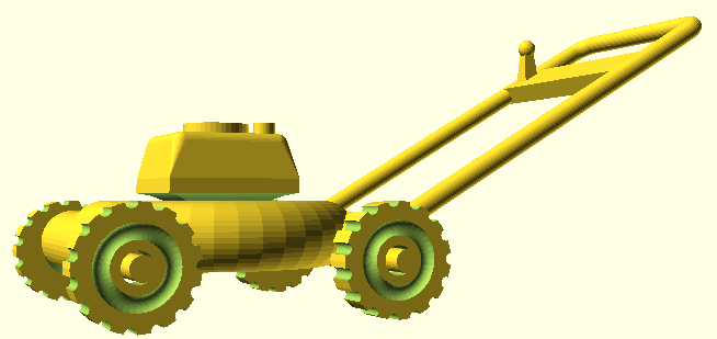
Lawnmower
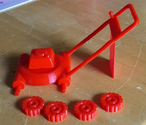
As spring sprouts new green things, the blades of lawn grass are among them. Homeowners and landscape companies have prepared their equipment for the season. This project is dedicated to my neighbor, Andy, who has already mowed our lawn twice, along with his own! Thanks, my friend.
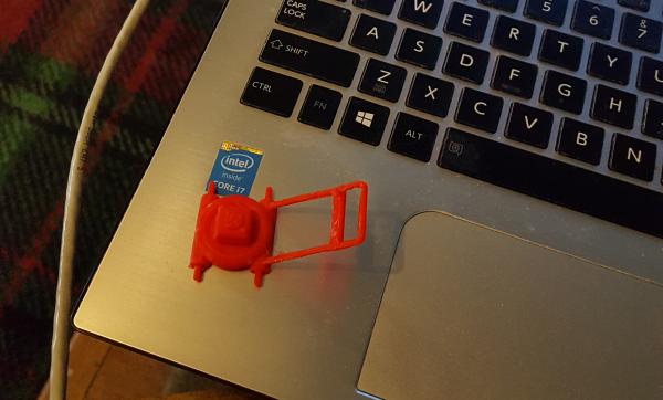
With proper social distancing, I passed the first successful prototype print to him. He immediately shared it with his young sons. Using PLA meant the model was strong enough to not break immediately. One nice thing about 3D printed toys is that they CAN be replaced if damage happens.
Design ideas come intermittently, but when one like this pops up, my tendency is to jump right into it. It means I am NOT thinking far ahead. I begin by working on what I think will be a challenging component and work out details using hand-coded values for the various parts. That means later changes potentially involves a lot of changes. Some day I'll learn / commit myself to plan ahead and think about using a base value to control dimensions in a much simpler way right from the start.
Rushing ahead early slows down later revisions. It is very tedious trying to track down which hard-coded values need to change (rotations do not, for example). Translations and sized components DO need to be changed.
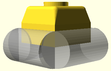
As I pushed on with version zero, I added more and more hard coded parts, eventually getting to the point of printing a test version.
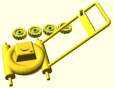
I didn't bother with wheels at first, but, in version01, I spent time adding simple cylinder wheels, and also set it up to make both a printable version along with one which put the wheels into a mock-up view. That's when parameter sizing began to be valuable. In the next code snippet, you can see how the placement of the wheels is appropriately spread out using the sz variable.
// show wheels in place
    if(display==1){
// left front wheel
        translate([-hhw-sz*3,-hhw-sz,sz])
    rotate([0,-90,0])
    wheel();
// right front wheel
        translate([hhw+sz*3,-hhw-sz,sz])
    rotate([0,90,0])
    wheel();
// left rear wheel
        translate([-hhw-sz*3,hhw+sz,sz])
    rotate([0,-90,0])
    wheel();
// right rear wheel
    translate([hhw+sz*3,hhw+sz,sz])
    rotate([0,90,0])
    wheel();
    }

    else

    for(i=[0:1:3]){
        translate([-sz*25,i*sz*11,0])
        wheel();
    }
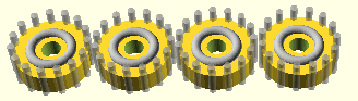
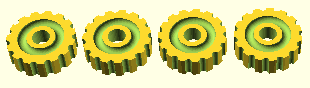
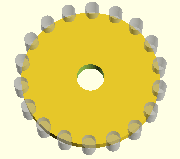
Version02 was also the stage when I added some wheel details to the wheel module. The tread worked out well, made from using difference to delete an even ring of cylinders around the perimeter of each wheel. Unfortunately, although the ring detail around the axle looks simple, it really slows down OpenSCAD's display performance. The preview becomes horribly unresponsive. Shifting the preview image around became extremely jerky and slow.
The ring, a torus, requires all the calculations of converting a 2D circle into 3D by rotation. It is apparently very calculation intensive. Every slight adjustment of the preview angle forces the torus to be recalculated. Therefore, I added a switch in the code to disable the little ring detail. It was driving me crazy while I tried converting the hard coded numbers all over the design into values controlled by a single size variable sz. Without the wheel detail, it also only takes 45 seconds to do the full render. The full (F6) render takes way longer.
Version02 took several trial-and-error hours to change the hard coded details in version one into values automatically adjusted based on the size variable. Now, I do realize that most printers and their slicer programs have the ability to do scaling. It is just that I DO want to keep myself on solid programming technique. Parametric programming is the OpenSCAD style!
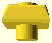
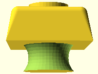
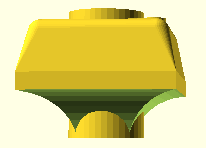
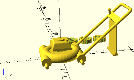
The engine box, at that stage, had a typically flat overhang which caused visible filament sag. Version03 added almost invisible support for the engine box. I considered using a ring to cut away around a cylinder, but that would again have added compile time in addition to jumpy preview. No thanks. A quick mock-up also showed it would not be really effective, still a lot of engine overhang. Another approach seems to work well, though. It removes four cylinders from an added cube, with a nice curving way to give effective support building out from the center to the edges of the engine overhang. The fourth image shows the cylinders with a nice OpenSCAD trick. Just add the special percent symbol (%) before each part you want to show, even if it is a removed part. It really helps to visualize where the parts are. No more sag under the box.
Eventually, the design looked "good enough" so I ran the full render and walked away so I would not fret about how long it would take, me just twiddling my thumbs in the meantime.
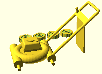
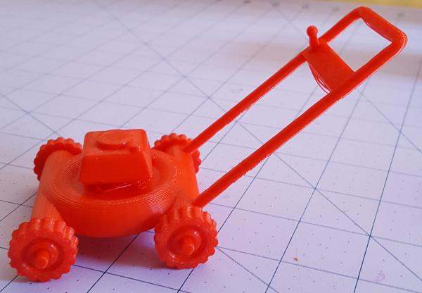
In the right hand photo (version03), you should just be able to see some filament sag across the low edge of the handle stiffener. I wanted to add a support, but had to do some work on my trigonometry skills to get the support to be in just the right place to be able to deal with using a different angle of the handle. It is currently set at 40 degrees, but you might like it at 35. Just set the ang=40; to your choice. The trigonometry is needed to make "your" support be automatically both shorter and further away from the engine.
Most coding languages change the spelling of trig values. Sine becomes sin() and cosine becomes cos().
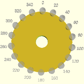
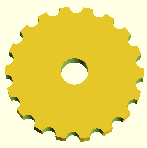
I've been using trigonometry's sine and cosine values in many projects over the years. For me, it has usually involved making a ring of objects like the cylinders used to make the tread on the wheels here. Entering the code for that comes quickly into my head, because it uses equal values for sine and cosine. Let's look at a quick example. The first image is produced by the code below the images. The second shows how the cylinder sine and cosine (angle) values move steadily (from 0 to 340 degrees in increments of 20 degrees) around the wheel's perimeter, and they cut through the edge of the wheel. The third image is the result. The cylinders have been removed from the wheel's edge by the difference() function.
The reason for stopping at 359 is to avoid duplicating the initial cylinder placed at zero degrees since 360 is in the same place. If you had an situation which needed steps smaller than one degree, you would need to adjust.
// Hard Coded circle of cylinders
// Not used "as is" in the project
// Compare to wheel module in scad file

$fn=40;
rad=10;
difference(){
cylinder(2,rad,rad); // the basic "wheel"
for(k=[0:20:359]) {
    // sine and cosine make a circle of cylinders
    // which are moved away from the center using
    // the radius (rad) as multiplier away from
    // the center of the wheel - equally.
    translate([sin(k)*rad,cos(k)*rad,-.1])
    %cylinder(4,1,1);  // visible because of the % modifier
   // axle hole
    translate([0,0,-.1])
    cylinder(4,2,2);
}
}
The % modifier is also very helpful when using the difference function, because you will be able to see where the "removed" objects are in case they are not exactly where you want them.
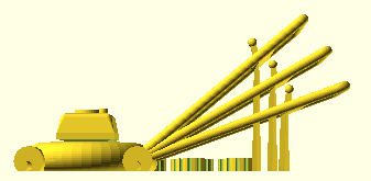
With the handle, the rotation occurs around the inner end of the handle where it attaches to the cowling. The support for the handle stiffener "mostly" rotates, but there's an offset to the back of the cowling. The next image shows three overlaid "handle and support" images at 40, 30 and 20 degrees rotation. Vertical adjustment for support is the Z axis. Horizontal is Y axis, as shown.
    if (display==0){
    hull(){
        // top of calculated handle support
        // cosine is the "horizontal" offset - Y value
        // cos(ang)*hl*.75+hhw - shifts away from cowling
        // hhw is the fundamental handle shift so it fits
        // without hhw, the handle would stick up at an angle from
        // the middle of the mower engine
        // sine is the "vertical" offset - Z value
        // sin(ang)*hl*.75 - shifts up to the handle stiffener
    translate([-hhw*.8,cos(ang)*hl*.75+hhw,sin(ang)*hl*.75])
       cube([hhw*1.6,.5,2]);
        // bottom of support
        // offset needed only for the horizontal Y value
    translate([-hhw*.8,cos(ang)*hl*.75+hhw-1,0])
       cube([hhw*1.6,2,2]);
    }
     //broader base for the support to avoid wobble
    translate([-hhw*.8,cos(ang)*(hl)*.75+hhw-4,0])
       cube([hhw*1.6,7,2]);
    }
Please Note: The axles slide easily through the wheel holes. I've used a hot knife blade to squash the end of each axle to keep the wheels on. It "works", but there may be a better way. I plan to experiment some more.
On a stock Lulzbot Mini using Cura for the slicer, the print at sz=2 used 3.89 meters of 3mm PLA and took 3 hours and 8 minutes.
"Everything's a Work in Progress."
Available Files:
SCAD files for study/modification and STL files for quick prints
GPL3 Licenselawnmower.scad - lawnmower.stl - current/latest stage of design