3D Central
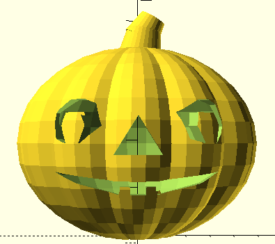
Halloween Jack o'Lantern
It is really too late to be posting this project for 2019. I didn't think about it until the morning of October 29th! But now you have until 2020 to work up your own versions!
This cut-out pumpkin has a few new tricks, so let's get started.
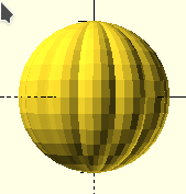
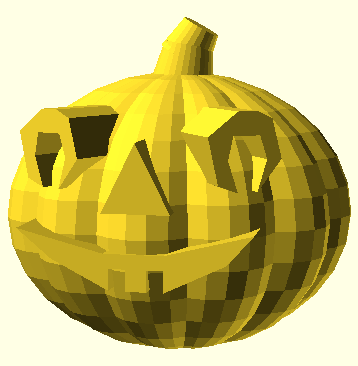
The basic pumpkin was made from a sphere, one which was rescaled laterally to make it a flattened shape like a Mento candy. I rotated and repeated the shape to make something which looked much like the segments of a pumpkin. As is, it is solid like a pumpkin before the messy work of turning it into a Jack o'Lantern, but it seemed like a good start.
module basic(){
for(x=[0:30:150]){
rotate([0,0,x])
scale([.5,1,1])
sphere(10); // In final code, the sphere size is "sz" instead of 10
}
}
I thought it looked too round and spheres center on all the X, Y and Z axes, so I squashed it down, shifted it up and sliced off the bottom so it would stand flat when printed. Since Jack o'Lanterns are hollow, I used difference() to accomplish that.
translate([0,0,sz*.8-1.5]) //  z=0
scale([1,1,.8]) // squash it
difference(){
basic();
    sphere(sz*.9); // remove insides
    translate([0,0,-sz])
    cylinder(2,sz/2,sz/2); // flat base
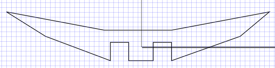
The eyes, mouth and nose are also removed from the pumpkin shape using difference() and 2D polygons which were extruded through the front side of the pumpkin. Making a polygon involves identifying points. I'm not too good at figuring that out in my head. This time, since the shapes are fairly complex, I resorted to using Inkscape because it is a program I use regularly. One of its features is a grid system which works very much like graph paper. If I didn't have Inkscape, I might have used regular graph paper to figure out the points of the polygons. I actually didn't use either when making the triangle of the nose, but a graph grid helped a lot when designing the mouth.
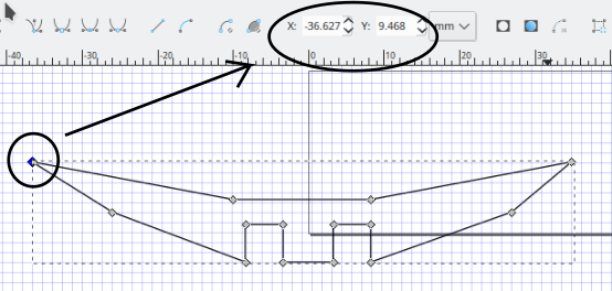
In general, it is wise to center any object you plan to use as components in 3D projects. It makes it much easier to position them where you want them. That means, after I had designed the shape of the mouth, I dragged it to be centered on the lower left corner of the Inkscape "bounding box". Then I proceeded counter-clockwise from point to point around the shape, recording them to use. The zero corner of the bounding box corresponds to the crossing spot of the X and Y axes in OpenSCAD. A polygon is a 2D object. To put it into a 3D project, we must do linear_extrude which converts the flat polygon into a solid. It is worth it to me to test the polygon alone and then to test its placement as a "positive" visible extrusion before trying it as a "negative" space as part of difference().
Conveniently, Inkscape lets us select each point, called a "node", showing their coordinates as each is selected. I will not try to cover the details of Inkscape processes. Inkscape may be a tool you decide to learn, but you can use regular graph paper for the same job.
The next step is to put the node point values into a polygon() instruction.
Even though this section is about the mouth, it will be a little easier to first look at the polygon code for the triangle nose with only three points. polygon([points],[paths],convexity) For every polygon, there are three elements: a series of "points", each described by the two numbers we collected from our graph paper; a list of the "paths" by listing our points' index numbers; and a convexity value. The punctuation is very picky. Notice that the whole set of points is in a pair of square brackets, while each bracketed point is separated by a comma from the next bracketed point, and that the path list is again enclosed with a double pair of square brackets. The convexity value is generally "safe" with a value of ten. Convexity basically is a count of how many times a straight line can cross through an "edge" of the polygon. In the illustration just below, you can see the blue line crosses an edge only six times. A value of ten is "safe" for most polygons I've used, and the extra convexity count does not noticably slow down the code.

linear_extrude(10)
    polygon (points=[[-5,0],[5,0],[0,10]], paths=[[0,1,2,0]],convexity=10);
Note that there are three neatly bracketed points for the triangle polygon making the nose, but that the path count of the point index numbers is four, closing back to the start index of zero. (Also notice that, as with most computer indexes, the very first item is zero. Computer languages almost always start indexing at zero instead of one.) Ensure a closed polygon by counting around "0,1,2,0" finishing back where you started. It keeps my brain comfy to start and stop with the zero, though I suppose it would work to count "1,2,3,0,1" instead. Want to try it? Go ahead!
module mouth(){
              linear_extrude(sz)
            polygon ( points=[[-36.6,9.4],[-25.9,2.8],[-8.3,-3.8],[-8.3,1.1],[-3.3,1.1],[-3.3,-3.8],[3.2,-3.8],[3.2,1.1],[8.2,1.1],[8.2,-3.8],[26.9,2.8],[34.8,9.4],[8.2,4.4],[-10,4.4]], paths=[[0,1,2,3,4,5,6,7,8,9,10,11,12,13,14,0]],convexity=10);
}
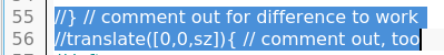
As mentioned earlier, it may help keep you (relatively) sane to try your positioning of parts in "positive" extrusion. When I try to work directly with difference(), I can be easily frustrated. All parts removed from the basic pumpkin are just not going to show, and if the positioning is off, it's hard to know. In my code, at the end of development, the lines 55 and 56 allowed me to make the eyes, mouth and nose visible by removing the comment (//) slashes which begin each line. When not commented out, the curly bracket stops the difference() before the eyes, etc. and the translate code adjusts the parts temporarily up to their final locations. During development, I actually work one part at a time, testing the positioning. I have not figured out how to do "plan ahead" perfectly. Maybe with time and practice.
Ultimately, for ease of reuse, most "component parts" are in modules. In this case, only the eye gets reused, but modules help to keep me organized. Once I got used to them, I have consistently employ them, if appropriate. I have also developed the habit of reorganizing my work so variables are defined early, modules come next and the linear execution of the project comes last. You are seeing the cleaned up version05 here. During earlier versions, things are a bit more chaotic. Let me know if it would help you to have access to earlier versions, too. See contact email in the footer of this page.
This project is built to be made bigger or smaller, each part adjusts based on the value assigned to the single variable for size, sz=30;. While my slicer program, Cura, has scaling built in, I have come to embrace trying to make my projects "parametric".
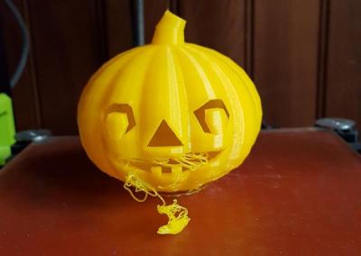
A half-size print looked pretty good, so I went for a 75% print, which took about 3½ hours, had a bit of unsurprising filament sag across the top of the mouth. I will see if I can do some supporting pegs along the gap in the mouth which I can then cut out with nippers. That's a step I'll do over the next few days and then update here.
Available Files:
SCAD files for study/modification and STL files for quick prints
jackolantern05.scad - jackolantern05.stl - appx. 6½ hr to print at sz=30 on Lulzbot MiniGPL3 License