3D Central
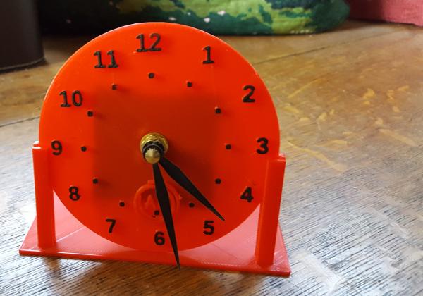
Simple Clock
This project started as just an exploration of how to get markers and hour numbers arranged in a circle. In some ways it didn't get much further, but I thought the exploration might be interesting to share.
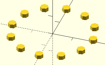
Positioning is accomplished by a two-part calculation of points. Specifically, we need sine and cosine values to arrange a series of objects.
// calulating a circle of dots

for(spot=[0:30:359]){
    translate([sin(spot)*20,cos(spot)*20,0])  // position control with radius multiplier
    cylinder(2,2,2);
}
Maybe it would be good to step back a bit. Let's look at the code for a sine wave all by itself. Perhaps you will recognize a typical sine wave from math class.
// calulating a sine wave

for(dot=[0:10:359]){
    translate([dot/5,sin(dot)*20,0])
    cylinder(2,2,2);
}
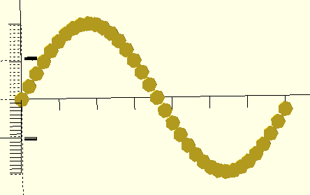
The sine, is called sin() as an OpenSCAD command. As the for loop of the code snip above increases from 0 to 359, our code adjusts the position of the dot on the y axis. The result is a set of dots making the sine wave some will recognize.
Now look at the cosine wave alone.
// calulating a cosine wave

for(dot=[0:10:359]){
    translate([cos(dot)*20,dot/5,0])
    cylinder(2,2,2);
}
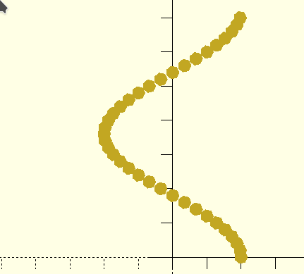
This time, as the y value increases step by step, the x value changes to create the cosine wave. The cosine is commonly shown using the cosine y value, but I've made it controlling the x value because it is the next step which combines cosine and sine control of the x and y positioning which makes a circle.
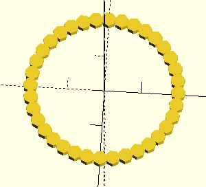
A loop step value of ten gives us overlapping dots. If we step a small step size, the circle will look solid. A larger step size spaces the dots. A step size of 30 gives us 12 dots which are conveniently placed just where the markers for a clock face need to go.
The multiplier of the x and y translation determines the radius distance from the circle's center.
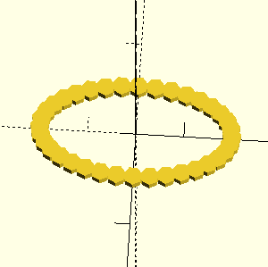
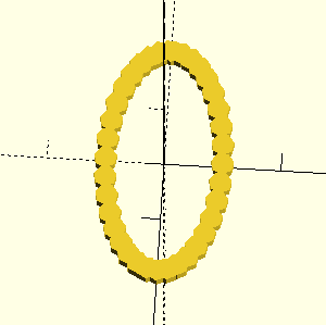
As a side note, using different multipliers of sine and cosine will make ovals. Experiment with the code snip to understand which mutiplier controls the dots to make either a wide oval or a tall oval.
The final SCAD code continues beyond just making 12 dots arranged 30 degrees apart around the circle. It adds the 12 numbers as well.
The loop count for(i=[30:30:359]) is used to print the right number in the right place. The little snip in the text extrusion code text(str(i/30) makes the numbers convert from a value to a text string AND it makes the value go from 1 to 12 instead of 30 to 360! Note, as well, that the starting point of the loop is 30 degrees from the top of the face. If we did the typical count from 0 to 359 in steps of 30 degrees the top number would be 0 and would go around to 11.
// Clock Face - Round
// version06 - 2019-01-05 - simplified code using align controls for numbers

// VARIABLES
$fn=30; // circle smoothness
thk=2.5; //thickness
rad=50; // face size control
// clock face is sized to fit my simple support
fnt=8; // adjust as needed for different radius sizes

//MODULES
module face(){
// it is important to note the start of numbers is at 30 degrees around to 360 so that the numbers go where they should be
for(i=[30:30:359]){
    // comment out next two lines to remove marker with .5 horizontal offset of half the marker width
    translate([sin(i)*rad*.6-.5,cos(i)*rad*.6-1,0])
    cylinder(thk*1.5,1,1);

// using halign="center" and valign="center is important because the default alignment is going to make numbers be out of place
        { translate([sin(i)*rad*.85,cos(i)*rad*.85,0])
    linear_extrude(thk*1.5){
        text(str(i/30), size=fnt, font="Liberation Sans:style=bold", halign="center", valign="center");
    }}
    }
}

// EXECUTE
difference(){
cylinder(thk,rad,rad); // round base for face of clock
    translate([0,0,-.1]) // cut through bottom layer
    cylinder(thk+1,4,4);} // adjust radius value  for actual clock movement shaft size
    translate([0,0,thk*.4])
    face();
You may have noticed that this is the sixth clock face version. Early versions were more complicated didn't use built-in text alignment controls. That made it harder to position everything. The first version was done in March of 2017, nine months earlier than this published file. Don't hesitate to revisit old code. I find that I learn more as time passes. Getting code ready to share offers me the chance to see if I can make the code easier to explain.
Alignment with halign and valign require us to specify the font name, even if using the default, built-in Liberation Sans font. Specifying the font also allows doing bold digits which I think are easier to read. In my printed version. I used black acrylic paint on the red PLA plastic to enhance legibility even more. I found white paint worked better on blue plastic as it would on black plastic, of course.
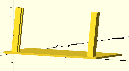
Designing a fancier case is an exploration I'll leave to you. I will share a simple support that this version of the clock fits. There's not much to it, so I will leave you the job of exploring the SCAD code on your own from the "cardstand.scad" file.
A quartz clock runs on a AAA battery is easy to find at a local craft store or online from vendors like https://www.klockit.com/. Verify the length of the stem so it fits the thickness of the clock face you make. A clock will often come with hands, but check the length of the minute hand to match your clock radius.
Available Files:
SCAD files for study/modification and STL files for quick prints
clockface06.scad - clockface06.stlcardstand.scad - cardstand.stl
GPL3 License