Chess Knight
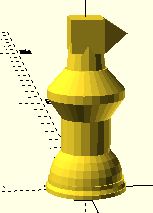
A short reminder that these notes build upon one another. Review the pawn, as necessary to understand the underlying structure of the design. This set of notes will concentrate on just the new top for the knight.
Right off, let's be clear that I'm new to 3D programming and decided to restrict myself to geometric forms while developing early projects. I am not very artistic, in any event, so I suspect a knight with a traditional horse face isn't happening any time soon.
There is nothing fancy about the "head", just a cube of equal 8mm dimensions in all three axes. The expansion of my effort was with the nose. I considered a cylinder, but it didn't look good AT ALL. Therefore, I challenged myself to try using a new shape command, a polyhedron. A polyhedron has the potential to be the most complex of OpenSCAD shapes. Fortunately this is a simple polyhedron, a small pyramid with just 5 sides/faces. It combines as many triangles as needed into "faces" to make a 3D shape. To make each triangle, you need to define a set of "points", one for each of the corners of the eventual shape. A very complicated shape is possible. What you see here is a simple shape, thank goodness.
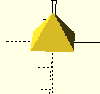
The points are defined by three numbers, one each for the X, Y and Z location of the particular apex/point of a triangle. To attach the "nose" to the cube of the "head", match up the base points of the nose with one side of the cube of the head. Build the shape flat and then later translate and rotate it into position at the top of the chess piece. In this case, I only needed five points to make a pyramid shape.
You do have to get a little geeky, here. After identifying the points, then build the triangles for the nose "faces" the first point isn't #1. The first point [4,4,0] is point zero (0), because of the geek thing. The next point, [4,-4,0] is point one (1) and so on. Because of that, the first face is defined by points 0, 1, and 4. Geeks and code rules count from 0 for the first element of any list instead of starting at 1. Get used to it.
Read through the faces code to try to trace the faces mentally or by drawing on paper what you think is going on. Because each face must be composed of triangles, the flat "base" of the pyramid has two triangles while the other three faces are already triangles. If you wanted to use a polyhedron to make a cube instead of using the built-in cube command, you would need to use two triangles for each of the six faces of the cube. Go ahead, try it; good practice!
 polyhedron(
  points=[ [4,4,0],[4,-4,0],[-4,-4,0],[-4,4,0], // the four points at base
           [0,0,6]  ],                                 // the apex point
  faces=[ [0,1,4],[1,2,4],[2,3,4],[3,0,4],              // each triangle side
              [1,0,3],[2,1,3] ]                         // two triangles for square base
 );
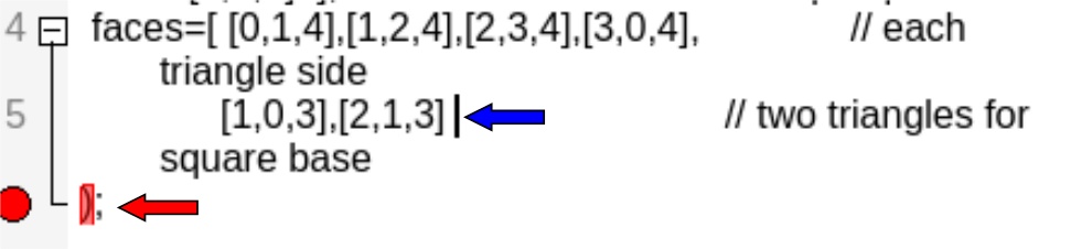
Be sure you notice that there are lots of square brackets involved in defining points and faces. Note the way the bracket pairs match around all the points as well as around each point. OpenSCAD will attempt to target your mistake if you miss a bracket. Unfortunately, it isn't always that accurate. The OpenSCAD editor displays a red circle where it identifies your first code error as it tries to compile the preview image.
In this case, it is close, but not that close. I have added a red arrow to point out that the editor sees an error "near" the closing curly bracket, but the error is actually at the vertical cursor marked by my blue arrow. I deleted the closing square bracket on purpose to show what happens with an error. The face brackets fail to match in this example.
If you are going to use OpenSCAD or any other programmatic design software, get used to fixing errors. Try to make lots of mistakes in the "syntax" of your simple shape practice. The more errors you see, the more quickly you will understand how to interpret the messages you get so you can later fix harder ones.
Note:
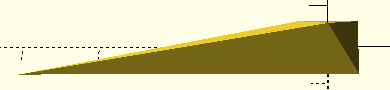
A final reminder about code errors. The editor will NOT identify all errors. Check the following code where a point on the x axis is entered as -40 instead of -4. Fortunately the misshapen part in the design preview window will probably help you see that a mistake has been made, especially one this big.
 polyhedron(
  points=[ [4,4,0],[4,-4,0],[-4,-40,0],[-4,4,0], // the four points at base
           [0,0,6]  ],                                 // the apex point
  faces=[ [0,1,4],[1,2,4],[2,3,4],[3,0,4],              // each triangle side
              [1,0,3],[2,1,3] ]                         // two triangles for square base
 );
Well, that's the set of notes for this design, the knight. Just in case you want to see it while reading this page, here's the correct code for the head/nose part of the chess piece. Download and examine the whole code for the knight with the SCAD file linked below.
// top section
translate([0,0,34])
    translate([-4,-4,0])
        cube(8,8,8);

// nose
translate([0,4,38])
rotate([-90,90,0])
        polyhedron(
  points=[ [4,4,0],[4,-4,0],[-4,-4,0],[-4,4,0], // the four points at base
           [0,0,6]  ],                                 // the apex point
  faces=[ [0,1,4],[1,2,4],[2,3,4],[3,0,4],              // each triangle side
              [1,0,3],[2,1,3] ]                         // two triangles for square base
 );
Available Files:
knight02c.scadknight02c.stl
GPL3 License