
Portable Workbench Crank
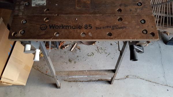
Over 20 years ago, I broke one of the hand cranks on my Black and Decker portable workbench. There was enough left of the lateral part of the crank that I could still turn it, and a locking pliers worked, too. Though I made a wooden replacement, it was not very good. For years, I let it slide.
The arrival of the 3D printer revived my interest. Besides, here was my chance to actually do a part replacement, a practical project!
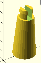
The basic components are cylinders, The only tricky bit was removing a rectangular slot in the handle to get it to fit into the hole of the crank.
To be able to remove the slot, the rest of the handle had to be done as a single piece. The difference() command needs a "parent" part from which the following "children" are removed. The hub shaft is the "parent". The pin hole "child" is removed from the shaft as is the other child, the central hole in the shaft. The large shaft hole goes onto the metal rod of the workbench to engage the clamping gear mechanism. To get the whole handle to be combined as a single "parent" we use the module name() command. First build the cylinder parts, just a stack of cylinders. Two of the cylinders do have different bottom and top diameter making them thinner at the top than the bottom, neat.
Then combine the stack of cylinders into a single shape, a "module". Then remove the slot from the parts which need the slot (the top two cylinders.
The module needs a unique name within a design. You get to choose the name yourself, but try to be descriptive with it to make the code easy to understand later.
Be aware, when you enclose a group of commands into a module, you must later "call" the module by name, here that call is hub(); to get it to create its shape. Modules are typically used more than once in a design. This time we only need one handle. The module code needs to be placed earlier in the program code than the calling (executing) of the module.
// crank handle
module hub(){
translate([0,25,0])
cylinder(40,12,8);
translate([0,25,0])
cylinder(45.5,6,6);
translate([0,25,45.5])
cylinder(3,6.5,6);
} // end of hub() module
// now do the difference of the slot from the hub
difference(){
    hub();
    translate([-8,22.5,40])
cube(size=[16,5,12], center=false);
}
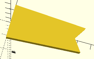
I am still in the early stages of doing 3D printing, so almost every new design gives me the chance to try some new function of the OpenSCAD software. The lateral arm of the crank needed a shape more complicated than a cube or cylinder. I wanted to have a close match to the existing crank and putting a hull around two cylinders at each end would not have quite done it. I wanted a slim section at the handle end. To get that narrowness, I decided to try my hand at an extruded polygon which did not fill the open hole for the handle neck.
// lateral crank arm
linear_extrude(height=5, convexity=10){
polygon(points=[[0,12.5],[53,9],[47,0],[53,-9],[0,-12.5]]);
}
Here's the final revelation: I was using white PLA filament while developing the crank. I'm so happy the crank works that I'm leaving the white one on the bench until it breaks, if ever.
Available Files:
crank.scadcrank.stl
GPL3 License